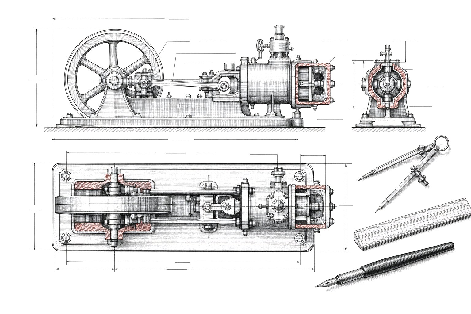
On this sheet / 7 parts
A general arrangement drawing is the sheet that shows the whole machine at once. Where a detail drawing describes one crank pin or one boiler plate, the GA drawing puts every part in its place, gives the overall sizes, and refers out to the detail sheets by number. For anyone working through a works archive it is the drawing to find first, because it explains what all the others are for. This guide covers how to read a general arrangement drawing from a British drawing office, roughly 1850 to 1970, when most of the surviving Manchester material was made.
What a GA drawing is for
Drawing offices split the work in two. Detail drawings told the pattern shop, the smithy and the machine shop how to make each component, with every dimension, tolerance and material. The general arrangement told the erecting shop how the components went together, and told the customer what they were buying. It carried overall dimensions, centres of wheels and shafts, clearances, and a list or key referring each part to its detail drawing.
That second audience matters. Railway companies and mill owners often received a copy of the GA with an order, which is why a GA drawing sometimes survives in a customer's papers when the maker's files have gone. The drawing archive guide explains where to look on both sides.
A locomotive GA from a firm such as Beyer, Peacock typically shows a side elevation of the engine, a plan, often split down the centre line into half plan and half section, and end views from front and back, sometimes with cross-sections through the firebox or smokebox. One sheet might be well over a metre long.
Views and projection
Each view is an orthographic projection: the object seen straight on from one direction, with no perspective. The front, or principal, view is called the elevation. The view from above is the plan. Views from the ends are end elevations or end views. Where the outside hides the important parts, the draughtsman cuts the object along a line and draws a section.
How those views are arranged on the sheet depends on the projection system, and anyone learning how to read a general arrangement drawing usually trips on this point first. British drawing offices historically used first-angle projection. Imagine the object sitting in front of a set of opaque walls. Each view is projected backwards onto the wall behind it, so the plan, seen from above, appears below the elevation, and the view from the left end appears on the right of the elevation. Third-angle projection, standard in North America and Japan, does the opposite: the plan sits above, and the left end view sits on the left.
The difference had real consequences. During the Second World War, British drawings for engines built in America, the Rolls-Royce Merlin among them, had to be converted to third-angle, and some British firms switched permanently afterwards. Modern sheets carry a small symbol in the title block, a truncated cone drawn in two views, that states which system is in use. Older sheets do not, so you work it out from where the plan sits.
Sections are marked on the parent view with a cutting line, a chain line with heavy ends and arrows, labelled with letters. Section A-A on the sheet is the view along that line in the direction of the arrows.
Scale, dimensions and lines
Large machines were drawn reduced. Imperial offices used ratios in inches to the foot: 3 inches to 1 foot is quarter size, 1½ inches to 1 foot is one eighth, 1 inch to 1 foot is one twelfth. The scale is written in the title block, and sometimes beside an individual view drawn at a different scale. Do not scale off an old print. Tracing cloth and paper shrink and stretch, and blueprints were made by contact through a tracing, so measured lengths drift. The written dimension is the one that counts.
Dimensions are given between extension lines with arrowheads, in feet and inches on large work and in inches alone on machine parts. A dimension in brackets is often for reference only, repeated from elsewhere for convenience.
Line types follow a code. A thick continuous line is a visible edge. A short-dashed line is hidden detail, an edge behind the surface you are looking at. A thin chain line of long and short dashes marks a centre line or a line of symmetry. Thin continuous lines carry dimensions, extension lines and hatching.
Hatching and materials
Cut surfaces in a section are hatched with thin parallel lines, normally at 45 degrees. Where two parts touch in a section, the hatching on each runs in opposite directions or at different spacing, so you can see where one ends and the next begins. Shafts, bolts, rivets and webs cut lengthwise are usually left unhatched by convention, which makes them stand out.
Older drawings sometimes coloured the cut faces instead, with watercolour washes to tell cast iron from wrought iron, brass or timber. Conventions varied between offices, so check whether the sheet carries a key before assuming what a colour means. Material is also given in words in the parts list or beside a part, often abbreviated as in the table below.
Title block, parts list and revisions
The title block, usually in the bottom right corner, is the drawing's identity card. Expect to find the firm's name, the drawing number, the title, the scale, the date, and the initials of the draughtsman, the tracer and the person who checked it. On a works drawing the drawing number links to the firm's drawing register, which is often the only surviving index to the office's output.
A GA usually carries a parts list or bill of materials, a table naming each item with its reference number, quantity, material and the number of its detail drawing. Balloons, small circles with a leader line, link each numbered part on the view to its line in the list.
Changes after issue were recorded in a revision block: a letter for each alteration, what changed, the date and initials. When several prints of one drawing survive, the revision letter tells you which is the latest. Workshop terms used in parts lists, such as fettled castings or patterns, are explained in the workshop glossary.
| Abbreviation or symbol | Meaning |
|---|---|
| A/F | Across flats (nut or bolt head size) |
| ASSY | Assembly |
| C/L or CL | Centre line |
| CRS | Centres (distance between centre lines) |
| CSK | Countersunk |
| DIA or ⌀ | Diameter |
| PCD | Pitch circle diameter |
| R | Radius |
| HEX HD | Hexagon head |
| CHAM | Chamfer |
| THD | Thread |
| BSW | British Standard Whitworth thread |
| C.I. | Cast iron |
| W.I. | Wrought iron |
| M.S. | Mild steel |
| G.M. | Gunmetal |
| DRG | Drawing |
| MATL | Material |
| Chain line (long and short dash) | Centre line or line of symmetry |
| Short dashes | Hidden detail |
| Truncated cone symbol | Projection system in use |
A GA in practice: the English Electric Lightning
The general arrangement of a jet fighter follows the same rules as a mill engine's. The English Electric Lightning, designed at the company's aircraft works at Warton in Lancashire under W. E. W. Petter and then F. W. Page, is a good example, because its oddest feature only reads in one view. Its two Rolls-Royce Avon engines sit one above the other in the fuselage: the plan view shows a slim body, while the side elevation shows two jet pipes stacked at the tail. The prototype P.1A first flew on 4 August 1954, the type entered RAF service in 1960, and it was the first British aircraft able to fly at twice the speed of sound in level flight. A Lightning GA sheet still carries a title block, a scale and a revision panel; what changes is the number of detail drawings behind it.
Tracings, blueprints and survival
The master of a general arrangement drawing was usually drawn in pencil on paper, then traced in ink onto tracing cloth, a cotton or linen fabric stiffened and glazed with starch. Tracing cloth was standard from about 1850 until polyester film replaced it from the 1950s. Its weakness is water: the starch attracts mould and the ink can run, which is why archives handle it carefully.
Copies were made by contact printing. Sir John Herschel published the cyanotype process in 1842, using iron salts that turn to Prussian blue on exposure to light, and from 1872 it was sold commercially for copying plans. The tracing was laid over sensitised paper in a frame and exposed, then the print was washed in plain water, leaving white lines on blue. These blueprints were the working copies sent to the shop floor, which is why surviving ones are often dirty, folded and annotated in pencil by fitters. Later diazo, or dyeline, prints gave dark lines on a pale ground.
From 1927 British practice had a written reference, BS 308, the first national standard for engineering drawing office practice. It began as 14 clauses and five illustrations, was revised in 1943, 1953, 1964 and 1972, and was eventually replaced by BS 8888. Drawings older than 1927 follow the habits of the office that made them, and those habits are part of what makes reading them interesting. A boiler GA for the Lancashire boiler from the 1870s and one from the 1950s can show the same object in quite different hands.