On this sheet / 7 parts
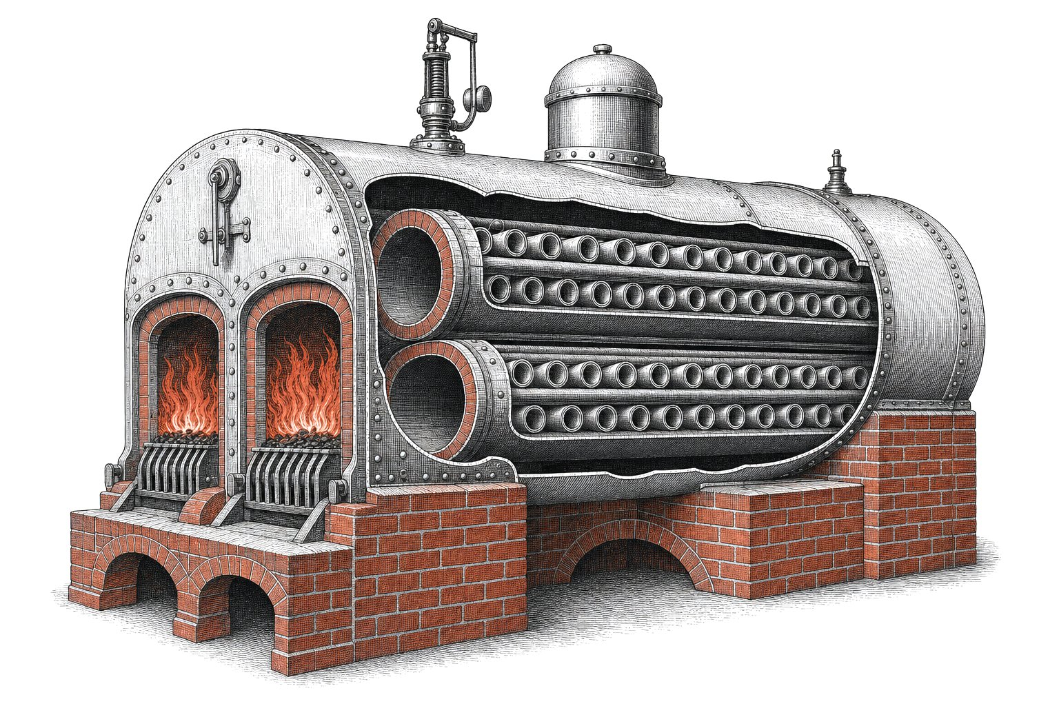
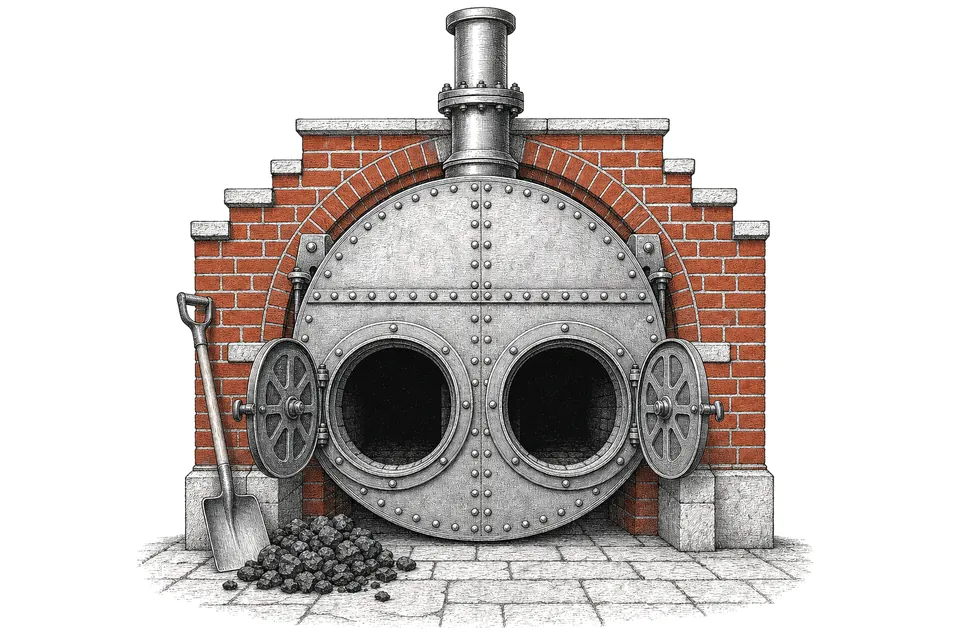
Walk into the boiler house of a Victorian cotton mill and you would usually find long cylindrical boilers lying in brickwork, each with two round furnace doors at the front. That arrangement is the Fairbairn Lancashire boiler, credited to William Fairbairn and John Hetherington in 1844. It was simple and large, and several could be set side by side to feed one mill engine.
Two fires in one shell
The Lancashire boiler grew out of the Cornish boiler, which Richard Trevithick first installed at Dolcoath mine in 1812. A Cornish boiler has one large flue running through a cylindrical shell of water, with the fire burning at the front end of it. The Lancashire design puts two flues side by side in the same shell. Its history begins with a simple aim: more steam from the same shell.
Two fires gave a bigger grate area and more heating surface. They also let the stoker fire one furnace while the other was burning bright, which cut smoke. The two flues did a structural job as well: they ran from end plate to end plate like a pair of long stays, holding the flat ends of the boiler against the pressure inside.
It became the standard boiler in Lancashire cotton mills, which is where the name comes from.
How it works: fire, flue and brickwork
In short, how it works comes down to hot gas passing the water three times before it reaches the chimney. Each furnace flue has an iron grate across its front end with a shallow ashpan underneath. The stoker throws coal through the furnace door onto the grate. Air comes in through the ashpan and, in the better designs, through a shuttered damper in the furnace door, a feature used from the 1840s, which helped the gases burn more completely.
The hot gases travel along the inside of the two flues to the back of the boiler. That is the first pass. They are not finished yet. At the back they divide, and half turn up each side to run forward along flues built in the brick setting, against the outside of the shell. At the front they drop into a single flue under the boiler and run back along its bottom to the chimney.
Three passes meant that the gases gave up much more of their heat before leaving. Some installations reversed the order, sending gases along the bottom flue first; that speeded water circulation but needed two dampers and only suited boilers with little sediment at the bottom.
Reading a Lancashire boiler diagram
Most published drawings show the boiler twice: a long section from the side and a cross-section from the front. In the cross-section, look for two large circles inside a bigger circle, and three smaller openings in the brickwork around it, two at the sides and one below. The table lists the parts you will find labelled on a typical Lancashire boiler diagram.
| Part | Where it sits | What it does |
|---|---|---|
| Shell | Outer cylinder | Holds the water and steam under pressure |
| Furnace flues (2) | Inside the shell, full length | Contain the fires and carry gases to the back |
| Grate and ashpan | Front of each flue | Hold the burning coal, admit air from below |
| Furnace doors | Front end plate | Firing and air control |
| Galloway tubes | Across the inside of the flues | Extra heating surface, stiffen the flue |
| Adamson joints | Between flue sections | Flanged joints that keep rivets out of the fire |
| Side flues (2) | In the brick setting, alongside the shell | Second pass of the gases |
| Bottom flue | In the brick setting, under the shell | Third pass, leading to the chimney |
| Damper | Before the chimney | Controls the draught |
| Safety valves | Top of the shell | Release steam above the set pressure |
| Stop valve | Top of the shell | Lets steam out to the engine |
| Water gauge and try-cocks | Front | Show the water level |
| Feed check valve | Shell | Admits feed water, stops it flowing back |
| Manhole | Top of the shell | Access for cleaning and inspection |
Fire a Lancashire boiler through one shift
Goal: weave 600 yards in a 90-second shift. Click a furnace (or press A / L) to shovel coal, and keep the needle in the green band, 150-170 psi.
From this sheet: older Lancashire boilers worked at about 60 psi; those feeding triple-expansion mill engines ran at 150 to 170 psi, and some were built for 200.
Sizes, pressures and Galloway tubes
The 1911 Encyclopaedia Britannica gives the usual length as 26 to 30 feet and the shell diameter as 6 and a half to 8 feet. The furnace flues were built in sections about 3 to 3 and a half feet long, welded along their length, flanged at each end and joined with Adamson joints, which kept rivets and doubled plate away from the fire and stiffened the tube like a series of rings. Any Lancashire boiler diagram from the period shows these flanged joints as a row of rings along each flue.
Pressures rose as mill engines improved. An older boiler worked at about 60 pounds per square inch, one feeding a compound engine at 100 to 120, and one feeding a triple-expansion engine at 150 to 170. Some were built for 200.
Galloway tubes, patented in 1848 or 1851, are short conical water tubes set across the inside of the furnace flue. Each is flanged at both ends and fixed to the flue plate, with one end slightly larger than the other so that a tube can be removed and replaced. They add heating surface, stiffen the flue, help the water circulate and stir the gases.
Economisers and the coal bill
Even after three passes, the gases leaving a Lancashire boiler were hot. In 1845 Edward Green patented an economiser: a bank of vertical cast-iron tubes, connected to water headers above and below, placed in the flue on the way to the chimney. Feed water passed through the tubes and the waste gases flowed around them, so the water reached the boiler already warm. Its most successful feature was a set of mechanical scrapers that kept soot off the tubes.
A history of explosions and inspection
The weakness of any shell boiler is the shell. Fairbairn's experiments with glass cylinders showed that the stress around the circumference of a cylinder under pressure is twice the stress along its length, so the seams running along a boiler carry the heavier load. That piece of arithmetic sits behind the whole history of boiler failures and inspection.
In 1854 engineers and mill owners met in Manchester to do something about explosions, with Fairbairn among them. The result, formally founded in 1855, was the Association for the Prevention of Steam Boiler Explosions and for Effecting Economy in the Raising and Use of Steam, later the Manchester Steam Users' Association. Members paid for their boilers to be inspected by an experienced engineer at regular intervals. Robert Bewick Longridge was chief inspector until 1858, and Lavington Evans Fletcher led the engineering work from 1862. The association became part of British Engine Boiler and Electrical Insurance in 1932.
Common misconceptions and where to look
The Fairbairn Lancashire boiler is often described as a patented invention. The 1844 patent, abstracted in 1845, actually covered a method of firing the two furnaces alternately to reduce smoke, and Robert Stephenson's Lancashire Witch locomotive had used twin furnace tubes about fifteen years earlier. Knowing how it works also explains why the brick setting was never decoration.
Its bulk for its length kept it to stationary work: nobody put one on wheels. A preserved Lancashire boiler can be seen at Pinchbeck Pumping Station in Lincolnshire. For what the steam did next, see from water to steam and the mill engines described on the Manchester cotton mills page; the locomotive boilers built across the city at Gorton are on the Beyer, Peacock page, and the work of James Joule explains how much useful work a pound of coal can give.